Basic Cutting Tool Inspection System with REACTION Software
For tools up to 1.00” (25mm) in diameter
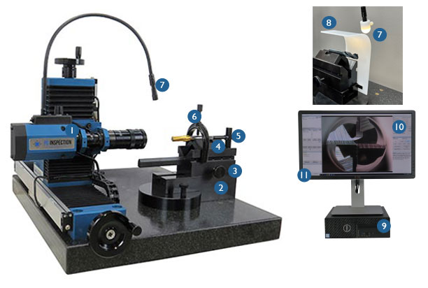
The PG1000-200 is a tool geometry inspection system durable enough for everyday shop floor use and precise enough for a metrology laboratories incoming and outgoing quality inspections. The 5MP camera reproduces and displays high resolution cutting tool images magnified up to 95x on a 4K monitor.
The PG1000-200 systems collect and display data from the horizontal (X), vertical (Y) and cross-hair rotation (Z) axes as well as allow for optional lighting control through the software.
Learn more on the detailed comparison between PG1000-200 and PG1000-400.
PG1000-200 System Includes
Unlike our competition, our proprietary REACTION software was designed specifically for the cutting tool industry with input from our customers. While many of our competitors use generic CAD software, which takes a screen shot of an image, the PG REACTION software allows the user to take measurements in real time without electronic pixel manipulation of the image assuring accurate and repeatable measurements down to the micron level.
The PG1000-200 REACTION software allows the user to measure tool geometries in multiple ways.
Once the tool and overly are aligned properly the DXF file can be locked to the scales and the DXF file will then follow the microscope allowing the user to visually inspect the entire geometry of the tool.
The PG REACTION software is very user friendly and and incorporates on screen prompts, instructions and video demos for each tool calculation. Calculations can be repeated efficiently by recalling previous saved inspection scenes. Annotations/notes can be added alongside measurements. With the click of an icon the software can export data to an Excel/CSV file or create a customized PDF report with results and user entered tolerances, images, customer details as well as an optional PASS/FAIL notification.
Features

| Specifications | |
|---|---|
| Scope Magnification | 15x, 20x, 30x, 40x, 55x, 75x, 95x |
| Maximum Tool Size | 0.075 - 1.00” (1.91 - 25mm), flute length up to 7.5” |
| Camera | 5 mega pixel color camera |
| Computer | High performance SFF with REACTION software preinstalled |
| Monitor | 27” 4K Ultra HD |
| Operating System | Windows 10 64 bit |
| Scales | Fagor 1µ |
| Power | 110Vac 60Hz (220Vac 50/60Hz optional) |
| Language | English, Spanish, Chinese, German, Japanese |
| Accuracy/Repeatability | +/-0.0002” (5µ) at maximum magnification |
| Measuring Range | Vertical: 2.75” (70mm) / Horizontal: 7.87” (200mm) horizontal |
| Dimensions | 24” W x 19” D x 18” H |
| Weight | 135 lb. |
Types of Measurements
50+ calculations/measurements available to choose from
Screen
Scales
Edge Detection
Concentricity fixture required for the following:
Comparisons
Applications
Types of Cutting Tools
Calibration Process
A precise calibration is the foundation for any accurate mechanical or optical inspection. Only after a proper calibration can accurate and repeatable inspection results be obtained. All PG1000’s are delivered having been factory calibrated, using proprietary certified glass reticles and a calibration process that is integrated in our REACTION software.
The calibration procedure follows ISO guidelines and produces a PASS/FAIL calibration report that shows ‘as found’ and ‘as calibrated’ values.
The PG1000 systems can be calibrated with either a standard or linear calibration reticle. Both the standard and linear reticles are available for rental or purchase. Both reticles calibrate the system at each zoom magnification.
The standard 1000-443 reticle will also calibrate the scales on the X-axis (horizontal) and Y-axis (vertical) over a 50x50mm area. This reticle works well for applications that require a relatively small designated measuring area.
When a larger measuring area is needed, it is important to calibrate at multiple points along the X- and Y-axes. The larger 1000-645 linear calibration reticle calibrates the scales on the X-axis every 10mm and on the Y-axis every 5mm over the entire 70x200mm measuring range.
For both reticles, accurate distance compensation values are saved and applied during tool inspection for each axis, assuring accurate distance measurement.
PG Inspection Technologies reserves the right to change specifications and designs without notice.
Illustrations, data, dimensions and weights given in this brochure and on our website are for guidance only and cannot be held binding on the company.
Have a question?
We’re here to help.